
- Home
- Product
- Types Of Transformer
- Single Phase Transformer
- Three Phase Transformer
- Distribution Transformer
- Power Transformer
- Inverter Transformer
- Solar Transformer
- Electric Arc Furnace Transformer
- Dry Type Transformer
- Amorphous Transformer
- Industrial Transformer
- Heat treatment transformer
- Environment Friendly Transformer
- Low Loss Transformer
- BIS Approved Transformer
- Star Rated Transformer
- Energy Efficient Transformer
- Type Test Transformer
- Ratings Transformer
- Types Of Transformer
- About
- Contact
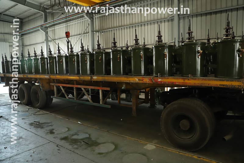
Single Phase Transformer manufacturer india
220v single phase to 3 phase transformer, single phase distribution transformer suppliers, view single phase variac, single phase auto transformer price in india and africa
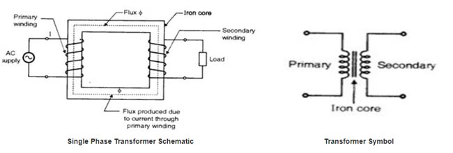
A Transformer is an electrical device that transforms the voltage of the current without changing the frequency. This is achieved by the two sets of coils. The primary winding is the coil that brings in electricity and the secondary winding is the one that brings the output out.
Single Phase Transformer Manufacturer India
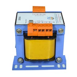
Single Phase Auto Transformer
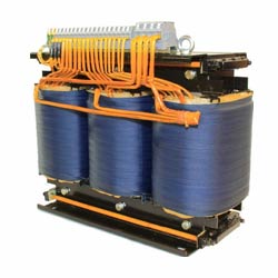
220v Single Phase To 3 Phase Transformer
Welding transformer single phase, single to 3 phase transformer, 220v single phase to 440 3 phase converter, single phase variac transformer, single phase variable transformer
The internal setup of the transformer produces and induction from the primary winding that initiates electric current in the secondary winding. Depending on the number of windings and their ratios between the primary and secondary, the voltage is either stepped up, or stepped down.
Single To 3 Phase Transformer
A single phase voltage transformer uses unified time phase electricity. In simple words, single phase electricity is used as the input. A Single to 3 Phase Transformer uses single phase as input and produces a 3 phase electric output. Single phase transformer manufacturers produce both single phase step up transformer and the single phase step down transformer. This type of transformers come in different capacities such as 220v Single Phase to 3 Phase Transformer and 220v Single Phase to 440 3 Phase Converter.
Types and characteristics of single phase transformers
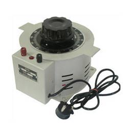
A Single Phase Variac Transformer can adjust the AC voltage continuously. The name stands for variable auto transformer. The AC waveform amplitude modulation gives a reliable control over the AC voltage from zero to line voltage. This is also called a Single Phase Variable Transformer. A Single Phase Distribution Transformer is used in distribution systems. These are used when there is practically no possibility to use 3 phase electric supply. These could be mounted on poles and pads. Usages include lighting, light commercial needs and domestic overheads.
Single Phase Auto Transformer is a special type of transformer in that it has only one set of coils. The primary and secondary coil windings are the same and a part of the coil does a double duty. Therefore, the size and weight of this transformer are less than conventional ones. It does not isolate the primary and secondary windings and is prone to short circuit effects. They have an increased VA rating due to their low excitation current, low loss and lower leakage resistance. This can also be used as a voltage regulator due to its functionalities. This kind of transformers are used in light weight applications often need to be mobile or portable.
Welding requires alternating current (AC) as output. Welding Transformer Single Phase is made specifically for welding purposes. When needed to be operating in DC, another type called a welding rectifier is used to get the AC output.
These can come in different capacities as well. 20kva single phase transformer, 5kva transformer single phase and others are available in the market. Rajasthan Powergen Transformer P. Ltd. is a Single Phase Transformer Manufacturer in India.
Single phase transformer definition
A single-phase transformer could be a sort of power transformer that utilizes single-phase rotating current, meaning the transformer depends on a voltage cycle that works in a bound together time phase.The most noteworthy voltage accessible in a single-phase organize is directed by utility foundation and mechanical regulations.Single-phase transformers are more well known than three-phase transformers in non-urban zones, as the cost of a three-phase distribution network is much higher, and the in general electrical request is lower.
Single-phase transformers with a 1:1 proportion can be utilized to disconnect circuits. Single-phase transformers stand by Ohm’s law, and exterior of minor characteristic misfortune due to warm, don’t make or evacuate power.High-voltage frameworks ordinarily utilize three-phase transformers to control flat buildings, retail centers, manufacturing plants, workplaces, and other large-scale structures

Single phase transformer specification
- single phase transformer Secondary current rating: rated output current
- Primary voltage rating: input voltage range; several nominal voltages represent more than one primary winding.
- single phase transformer Secondary voltage rating: output voltage range
- Operating frequency range: transformers with high operating frequencies tend to be smaller, as fewer windings are needed to match impedances.
- Operating temperature: safe temperature range of a transformer in operation; transformer temperatures rise while in use.
- Power rating (VA): maximum voltage suitable for a transformer, expressed in volts-amps.
- single phase transformer Standard
- ANSI C57.12.21 – Single-phase, high voltage, pad-mounted distribution transformers
- ANSI C57.12.25 – Single- and three-phase, liquid-filled distribution transformers
- IEC 62505-3-2 – Traction railway systems using single-phase transformers
- Single Phase Transformer Manufacturers Export to: India, Africa, Kenya, Malawi, Nigeria, Tanzania, Uganda, Rwanda, Bangladesh, Nepal, Malaysia
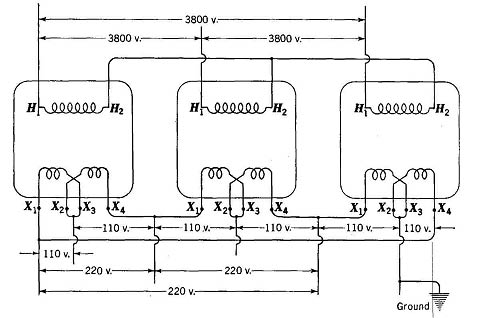
Single phase to three phase transformer diagram
emf equation of single phase transformer
φ= φm sin ω t
The instantaneous e.m.f. induced in a coil of T turns linked by this flux is given by Faraday’s law as
The above equation for Single Phase Transformer can also be written as
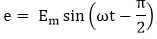
Where Em = Tωφm =maximum value of e.
For sine wave, the r.m.s. value is given by
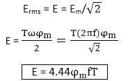
Erms = E = Em/
This is called as e.m.f. equation of transformer.
Where,
- φm is the maximum flux in webers (Wb)
- f is the frequency in hertz (Hz)
- E is the voltage in volts
- T is number of turns in winding
The primary r.m.s. voltage is
- E1 = 4.44φm fT1
The secondary r.m.s. voltage is
- E2 = 4.44φm fT2
Single phase step up transformer:These are the transformer in which the yield voltage is higher than the input voltage.
Single phase step down transformer:These are the transformer in which the yield voltage is less than the input voltage.
single phase transformer price
For Final single phase transformer price India Please Mail Us on info@rajasthanpower.in
single phase transformer manufacturers
single phase transformer manufacturers, 2 phase to 3 phase transformer, 20kva single phase transformer, 5kva transformer single phase, get single phase to 3 phase transformer converter
EMS Simulation of a Single-phase transformer
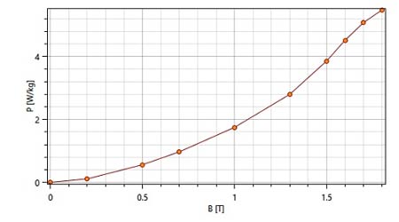
In EMS, a single-phase transformer is analyzed utilizing AC Magnetic consider coupled with thermal examination to calculate the core loss, magnetic flux thickness and temperatures.The properties of the materials are summarized
| Component | Material | Relative permeability | Electrical Conductivity (S/m) | Thermal Conductivity (W*m-1 * k-1) |
| Core | laminated steel (M36 at 0.47mm; Mass density: 7700 kg/m^3) | 1616 | 2.32558 e+006 | 43 |
| Inner Coil/ Outer Coil | Copper | 0.99991 | 5.7e+007 | 401 |
| Coils Air, Inner Air, Outer Air | Air | 1 | 0 | 0.024 |
Meshing
Meshing may be a very crucial step within the recreation. EMS estimates a worldwide component measure for the model taking into consideration its volume, surface zone, and other geometric points of interest
| Name | Mesh size | Components /Bodies |
| Mesh control 1 | 25.40 mm | Inner Coil, Outer Coil |
| Mesh control 2 | 25.40 mm | Coils Air |
| Mesh control 3 | 50.80 mm | Inner Air |
| Mesh control 4 | 50.80 mm | Core |
single phase transformer rating
Calculation of kVA capacity for a Single Stage Transformer, based on Winding Voltage and Amperage data.
To decide kVA you must have at slightest two pieces of data:
- the load line-to-line voltage (V)
- the maximum load phase current (I)
Single Phase Transformers: kVA = (V * I) /1000
Single Phase Transformer Example: V = 240, I = 175; Therefore: kVA = (240 x 175) / 1000 = 42 kVA
| Description | Max Ratings | Voltages | Standards |
| Single-phase Pole mount Distribution Transformers | 315 kVA | Up to 36 kV | ANSI,IEC,IS |
single phase transformer equivalent circuit
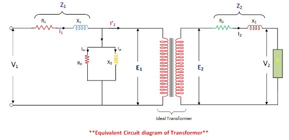
Where,
- R1 = Primary Winding Resistance.
- R2= Secondary winding Resistance.
- I0= No-load current.
- Iµ = Magnetizing Component,
- Iw = Working Component,
This Iµ & Iw are connected in parallel across the primary circuit. The value of E1 ( Primary e.m.f ) is obtained by subtracting vectorially I1 Z1 from V1 . The value of X0 = E1 / I0 and R0 = E1 /Iw. We know that the relation of E1 and E2 is E2 /E1 = N2 /N1 = K , ( transformation Ratio )
From the equivalent circuit , we can easily calculate the total impedance of to transfer voltage, current, and impedance either to the primary or the secondary.
working principle of single phase transformer
The working principle of the single phase transformer is based on the Faraday’s law of electromagnetic induction. Basically, mutual induction between two or more windings is responsible for transformation action in an electrical transformer.
According to Faraday’s law, “Rate of change of flux linkage with respect to time is directly proportional to the induced EMF in a conductor or coil”.
The working principle of single phase transformer has been explained in the following simple steps:
- As soon as the primary winding is connected to a single–phase supply, an AC current starts flowing through it.
- An alternating flux is produced in the core by the AC primary current.
- The alternating flux gets linked with the secondary winding through the core.
- Now, according to Faraday’s laws of electromagnetic induction this varying flux will induce voltage into the secondary winding.
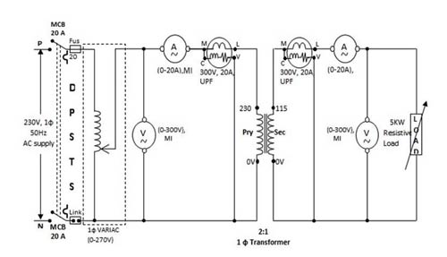
load test on single phase transformer
Method for the load test
- Make connections as per the circuit diagram.
- Switch on the supply and apply the rated voltage of secondary winding by varying the autotransformer.
- Note down the ammeter, voltmeter, and wattmeter reading for the no-load condition.
- Switch on the load and apply the load in steps up to the rated secondary current.
- Note down the ammeter, voltmeter and wattmeter readings for each step of the
- Reduce the load and then switch off the supply.
- Tabulate the readings and perform necessary calculations with the given formula to find efficiency and regulation.
construction of single phase transformer
A single-Phase transformer comprises of essential and auxiliary winding. The center of the transformer is made of thin sheets (called laminations) of high review of silicon. These laminations are given within the transformer to decrease eddy-current misfortune, and the silicon steel decreases hysteresis loss. The laminations display within the transformer are protects from one another by warm safe finish coating. L – Type and E- type laminations are utilized for developments.
There are two essential types of transformer constructions:
- Core type construction single phase transformer.
- Shell type construction single phase transformer.
Shell type construction single phase transformer
Within the shell type transformer, both the essential and auxiliary winding are injured on the central limb, and the low reluctance way is completed by the external appendages. Each winding is subdivided into areas. Low voltage (lv) and High voltage (hv) subsections are then again set within the form of sandwich that’s why this winding is additionally called sandwich or disc winding.
Core type Construction single phase transformer
Within the core type transformer, the magnetic circuit comprises of two vertical legs or limbs with two horizontal sections, called yokes. To play down the leakage flux, half of each winding is put on each leg of the core. The low voltage winding is put following to the core, and the high voltage winding is set around the low voltage winding to decrease the protection fabric required. In this way, the two winding are orchestrated as concentric coils. Such type of winding is called as concentric winding or cylindrical winding.
The core is made up of two types of laminations. The laminations for the core type are U, and I formed. Firstly the U- formed laminations are stacked together for the specified length. Half of the prewound low voltage coil is set around the limbs. The lv coil is advance given with cover. At that point half of the prewound hv coil is put around the lv coil. The core is at that point closed by the I-shaped laminations at the top.
parallel operation of single phase transformer
Parallel Operation of a Single Phase Transformer implies that the two or more transformers having same polarities, same turn proportions, same stage arrangement and the same voltage proportion are associated in parallel with each other.
The circuit graph of two single phase transformer A and B associated in parallel are appeared below
Let,
- a1 is the turn ratio of the transformer A
- a2 is the turn ratio of the transformer B
- ZA is the equivalent impedance of the transformer A referred to secondary
- ZB is the equivalent impedance of the transformer B referred to secondary
- ZL is the load impedance across the secondary
- IA is the current supplied to the load by the secondary of the transformer A
- IB is the current supplied to the load by the secondary of the transformer B
- VL is the secondary load voltage
- IL is the load current
Applying Kirchhoff’s Current Law
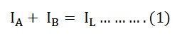
By Kirchhoff’s Voltage Law
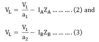
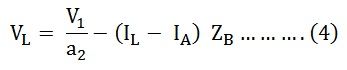
Now putting the value of IB from the equation (1) in equation (3) we will get
Solving equations (2) and (4) we will get
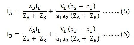
The current IA and IB has two components. The primary component speaks to the transformers share of the load currents and the second component may be a circulating current within the secondary windings of the single phase transformer.
oc and sc test on single phase transformer
These circuit parameters are provided in terms Open Circuit (OC) and Short Circuit (SC) test information of a transformer. Without really loading the transformer, these two assessed tests deliver the test results which are utilized to decide the identical circuit parameters.
Open Circuit or No Load Test on Transformer
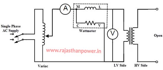
This test is performed to discover out the shunt or no load department parameters of comparable circuit of a transformer. This test comes about the iron misfortunes and no load current values, subsequently we are able decide the no load department parameters with basic calculations.The OC test is carried out by interfacing LV side (as essential) of the transformer to the AC supply through variac, ammeter and wattmeter rebellious. The auxiliary side or HV side terminals are cleared out open and in a few cases a voltmeter is connected over it to degree the auxiliary voltage.
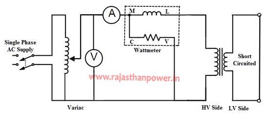
Short Circuit Test on Transformer
one phase transformer Features
- Indoor/outdoor rated: the transformer is specified for certain operating environments. Oil-filled transformers are almost always installed outside.
- Flameproof: the transformer has enhanced fire resistance, which is useful in potentially-reactive environments such as mines.
- Current limiting protection: an overcurrent protection mechanism.
- NEMA enclosure: the transformer casing or container conforms to a NEMA rating, a standard regarding ingress protection for various industrial and environmental contaminants.
- Submersible: transformer can be submerged.
- Tamperproof: the transformer cabinet retains a lock or other vandal-resistant mechanism.
- Waterproof: transformer has a sealed case to prevent water intrusion.
types of transformer available
single phase transformer parts
The three main parts of a single phase transformer are:
- Primary Winding: The winding that takes electrical power, and produces magnetic flux when it is connected to an electrical source.
- Magnetic Core: This refers to the magnetic flux produced by the primary winding. The flux passes through a low reluctance path linked with secondary winding creating a closed magnetic circuit.
- Secondary Winding: The winding that provides the desired output voltage due to mutual induction in the transformer.
1 phase transformer application
- non-urban areas where electrical demand is lower
- commercial and residential lighting and heating equipment
- step-down localized power distribution
- step-up power in home inverters
- television sets to regulate voltage
- low voltage electronic devices
single phase transformer for sale
|
|
2 phase to 1 phase transformer, single phase step up transformer, 50 kva transformer single phase, single phase to 3 phase transformer, 3kva transformer single phase, single phase step down transformer, single phase voltage transformer
two phase to single phase transformer, single phase to three phase transformer, 2 phase to single phase transformer, see 10kva transformer single phase, 5kva single phase transformer price
types of transformer available
- Single Phase Transformer
- Three Phase Transformer
- Distribution Transformer
- Power Transformer
- Inverter Transformer
- Solar Transformer
- Dry Type Transformer
- Amorphous Transformer
- Industrial Transformer
- Electric Furnace Transformer
- Heat treatment transformer
- Environment Friendly Transformer
- Low Losses Transformer
- BIS Approved Transformer
- 3 Star Transformer
- 4 Star Transformer
- 5 Star Transformer
- Energy Efficiency Level 2
- Energy Efficiency Level 3
- CPRI Aprroved Transformer
- ERDA Approved Transformer
- 1 MVA Transformer
- 1.5 MVA Transformer
- 2 MVA Transformer
- 2.5 MVA Transformer
- 3.15 MVA Transformer
- 5 MVA Transformer
- 8 MVA Transformer
- 10 MVA Transformer