power transformer manufacturers in india
An Authorized electrical power transformers, 12v transformer, step down transformer 230v to 12v, dc transformer, ac transformer suppliers in africa, view 24v transformer
price
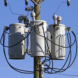
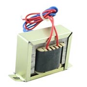
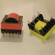
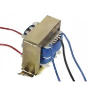
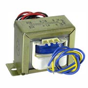
Electrical Power Transformers are devices that transform the electricity. A transformer could be either an AC transformer or a DC transformer. Power Line Transformer or Control Power Transformer can be used either as a step down voltage converter such as step down transformer 230v to 12v.
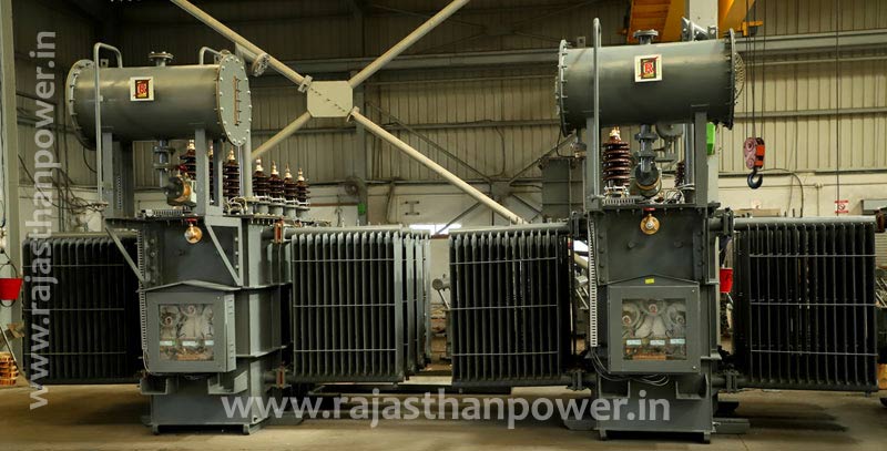
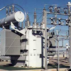
power transformer manufacturers in india
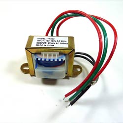
12v transformer
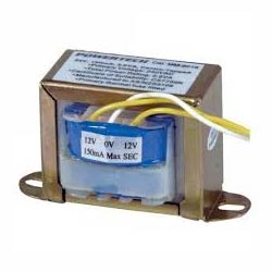
step down transformer 230v to 12v
Looking For power line transformer, control power transformer and oxygen not included power transformer, 5 mva transformer, power transformers exporter in india, view ac to dc power transformer
manufacturers in India
Transformers come in different capacities such as 12v Transformer, 24v Transformer, 5 Mva Transformer, 110v to 220v converter, 220 to 110 voltage converter, 220 to 110 voltage converter, 11kv transformer, and many more. An Ac To Dc Power Transformer converts power from alternating current to direct current. A Step down Transformer 230v to 12v is something that converts or steps down a 230v electric current into a 12v electric current.
Lighting transformer as the name implies is used in lighting systems. This can be domestic, industrial or commercial. Lights usually operate at lower voltages compared to the mains power. So this transformer reduces the voltage from the 3phase mains to a single phase load to the lights.
Power Transformer Manufacturers in India produce many different types of power transformers. The pricing differs per product type, make and model. Some Indian companies provide very competitive pricing for transformers. Electric transformer price would be less and the quality would be high at better manufacturers like Rajasthan Powergen Transformer P. Ltd.
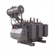
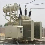
Power transformers operate at high voltages and generally at transmission networks. When used in transmission substations, it is called as a Substation transformer. They have higher insulations and bigger sizes because they operate at bigger loads. These devices are designed to operate all day long with less specific weight. In transmission networks, the power transformers are often used to step up the electricity to be supplied over the main supply. They have higher flux density. Their specific design enables them to operate near 100% efficiencies as their load is always full at the power generation plants.
Power transformers come in small, medium and large categories. The small ones range from about 500 to 7500kVA, the medium range is up to 100MVA and the large ones go beyond this capacity. A power transformer could last on average a 30 year lifespan.
A power transformer may be a inactive electromagnetic gadget that exchanges vitality from one circuit to another circuit by implies of inductive coupling. Power transformers contrast from other transformer types in that they are planned to comply with administrative prerequisites for mains power interfacing, working at mains voltages and moderately high currents.Power transformers are generally utilized in transmission network for stepping up or down the voltage level.
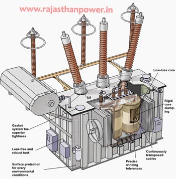
It works basically during high or top loads and has greatest efficiency at or near full load. Power Transformer is for the most part appraised at Higher MVA(>200MVA)and it is utilized in stepup and step down application in Transmission,whereas distribution transformer used in distribution.It is one of the foremost common electrical equipment with a diverse measure than we are utilizing in our lifestyle form morning to night.
- The range of small power transformers can be from 500-7500kVA
- The range of medium power transformers can be from -100MVA
- The range of large power transformers can be from 100MVA & beyond
- power transformers Phase is 3Ø
- Frequency of power transformers if 60Hz,50Hz
- power transformers Primary Voltage is 22.9 kV
- power transformers Secondary Voltage is 6.6/3.3 kV
- Tap Voltage of power transformers 23.9-R22.9-21.9-20.9-19.9kV
- power transformers Vector Dd0, Dyn11, etc.
- power Transformer Manufacturers Export to: Rwanda, Uganda, Kenya, India, Malawi Malaysia Bangladesh, Tanzania, Nepal, Nigeria, Africa,
The most rule of operation of a transformer is common inductance between two circuits which is connected by a common magnetic flux. A fundamental transformer comprises of two coils that are electrically isolated and inductive, but are magnetically connected through a way of hesitance. The working guideline of the transformer can be caught on from the figure underneath.
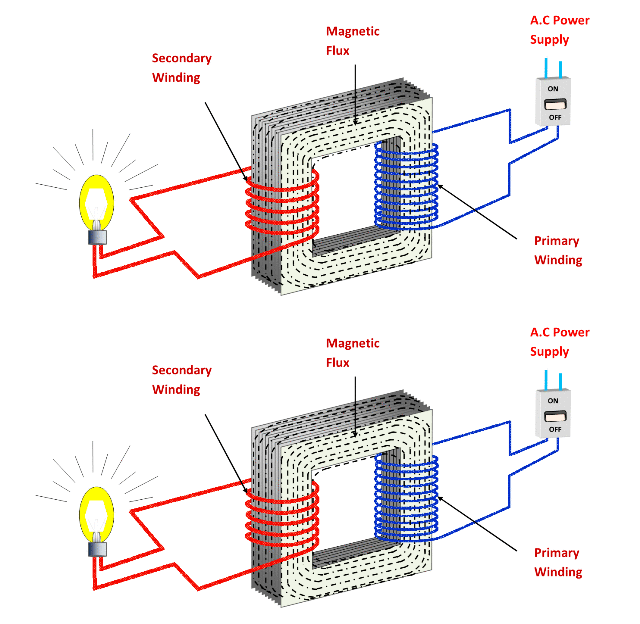
As appeared over the electrical transformer has essential and auxiliary windings. The core laminations are joined within the shape of strips in between the strips you’ll see that there are a few limit crevices right through the cross-section of the center. These staggered joints are said to be ‘imbricated’. Both the coils have high mutual inductance. A common electro-motive force is initiated within the transformer from the alternating flux that’s set up within the covered core, due to the coil that’s associated to a source of rotating voltage.
In brief, a power transformers carries the operations appeared below:
- Transfer of electric power from one circuit to another.
- Exchange of electric power without any alter in frequency.
- Transfer with the guideline of electromagnetic induction.
- The two electrical circuits are connected by common acceptance.
| Description | Max Ratings | Voltages | Standards |
| Autotransformers | 20 MVA | Up to 36 kV | ANSI,IEC,IS,BS,NEMA |
| Generator Step-up Transformers | 20 MVA | Up to 36 kV | ANSI,IEC,IS,BS,NEMA |
| Small Power Transformers | 20 MVA | Up to 26 kV | ANSI,IEC,IS,BS,NEMA |
For Final power transformer price Please Mail Us on info@rajasthanpower.in
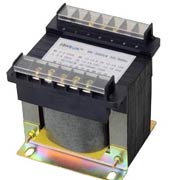
control power transformer
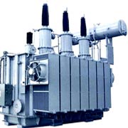
oxygen not included power transformer
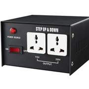
220 to 110 voltage converter
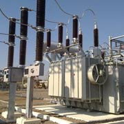
Substation transformer
Find Great Deals On 110v to 220v converter, smps transformer, voltage transformers & regulators, substation transformer 220 to 110 voltage converter, check electric transformer price
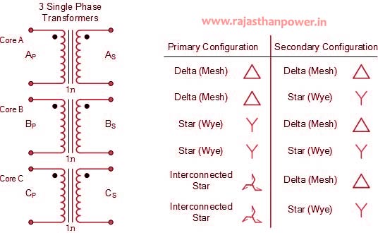
The power transformer comprises three transformers either isolated or combined with one core.There are four conceivable connections for power transformers
- Δ – Δ (Delta – Delta) power transformers Connection
- Υ – Υ (Star – Star) power transformers Connection
- Δ – Υ (Delta – Star)power transformers Connection
- Υ – Δ (Star – Delta )power transformers Connection
Power transformers Winding Identification
| Connection | Primary Winding | Secondary Winding |
| Delta | D | d |
| Star | Y | y |
| Interconnected | Z | z |
Υ – Υ (Star – Star) Power transformers Connection
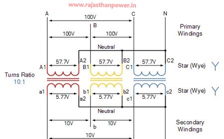
- Star-star connection is generally used for small, high-voltage transformers. Because of star connection, number of required turns/phase is reduced (as phase voltage in star connection is 1/√3 times of line voltage only). Thus, the amount of insulation required is also reduced.
- The ratio of line voltages on the primary side and the secondary side is equal to the transformation ratio of the transformers.
- Line voltages on both sides are in phase with each other.
Delta-Delta (Δ-Δ) Power transformers Connection :
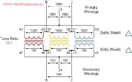
- This connection is generally used for large, low-voltage transformers. Number of required phase/turns is relatively greater than that for star-star connection.
- The ratio of line voltages on the primary and the secondary side is equal to the transformation ratio of the transformers.
- This connection can be used even for unbalanced loading.
Υ – Δ (Star – Delta )Power transformers Connection (OR Wye-Delta)
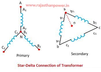
- The primary winding is star star (Y) connected with grounded neutral and the secondary winding is delta connected.
- This connection is mainly used in step down transformer at the substation end of the transmission line.
- The ratio of secondary to primary line voltage is 1/√3 times the transformation ratio.
- There is 30° shift between the primary and secondary line voltages.
Δ – Υ (Delta – Star) Power transformers Connection(OR Delta-Wye (Δ-Y))
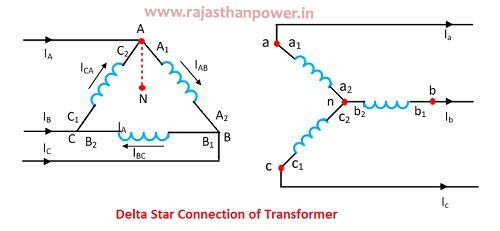
- The primary winding is connected in delta and the secondary winding is connected in star with neutral grounded. Thus it can be used to provide 3-phase 4-wire service.
- This type of connection is mainly used in step-up transformer at the beginning of transmission line.
- The ratio of secodary to primary line voltage is √3 times the transformation ratio.
- There is 30° shift between the primary and secondary line voltages.
Power transformers Line Voltage And Current
| Primary-Secondary Configuration |
Line Voltage Primary or Secondary |
Line Current Primary or Secondary |
| Delta – Delta Power transformers |
|
 |
| Delta – Star Power transformers |
|
 |
| Star – Delta Power transformers |
 |
 |
| Star – Star Power transformers |
|
 |
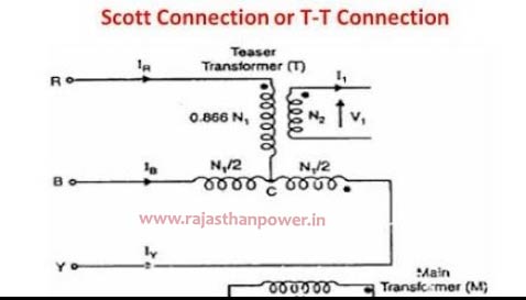
Scott (T-T) Power transformers Connection
Two transformers are utilized in this type of association. One of the transformers has middle taps on both essential and auxiliary windings (which is called as primary transformer). The other transormer is called as teaser transformer. Scott connection can moreover be utilized for three phase to two phase transformation.
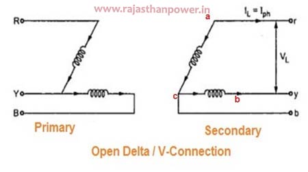
Open Delta (V-V) Power transformers Connection
Open delta association can be utilized when one of the transformers in Δ-Δ bank is debilitated and the benefit is to be proceeded until the defective transformer is repaired or supplanted. It can too be utilized for little three phase loads where establishment of full three transformer bank is un-necessary.
power transformers connection diagram
K-factor could be a weighting of the harmonic load currents agreeing to their impacts on transformer warming, as determined from ANSI/IEEE C57.110. The higher the K-factor, the more prominent the harmonic warming impacts. There are numerous distinctive loads such as computers, solidstate gadgets and engines which cause a non direct load. These type of loads create harmonic currents that cause transformers and system neutrals to overheat, which can crush the transformer.
For calculating the K-factor all the sounds up to a predefinedlimit are considered. For mechanical loads of acceptance engines, up to 25th harmonic currents are considered but the constrain can be up to 50th.As from the equation, The formula for calculating the K factor of a network is
![]()
whereas calculating the K-factor, the harmonic current is getting duplicated by the square of its number.
To determine kVA you must have at least two pieces of information:
- the load line-to-line voltage (V)
- the maximum load phase current (I)
Single Phase Transformers: kVA = (V * I) /1000
Three Phase Transformers: kVA = (V * I * 1.732) / 1000
Single Phase Transformers Example: V = 240, I = 175; Therefore: kVA = (240 x 175) / 1000 = 42 kVA
Three Phase Transformers Example: V = 208, I = 175; Therefore: kVA = (208 x 175 x 1.732) / 1000 = 63.05kVA
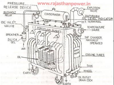 These are the basic components of a Power transformers.
- Laminated core
- Windings
- Insulating materials
- Transformer oil
- Tap changer
- Oil Conservator
- Breather
- Cooling tubes
- Buchholz Relay
- Explosion vent
we offers a wide extend of accessories to improve security, decrease maintenance and screen the execution of power transformers.
|
Magnetic oil level indicator |
High voltage and low voltage bushings |
|
Oil temperature indicator |
Hot dipped galvanized radiators |
|
Drain valve and oil sampling valve |
Lifting lugs on tank (for lifting complete oil-filled transformer) |
|
Oversized type 3R control box |
Lifting lugs on cover (for lifting cover only, if necessary) |
|
Mechanical pressure relief device |
Jacking facilities at each corner of the transformer base |
|
Diagrammatic aluminum nameplate |
Fall protection system |
There are two types of Power transformers testing
Open Circuit or No Load Test on power Transformers
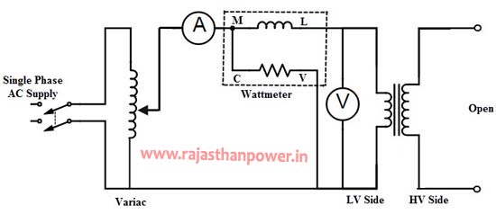
This test is performed to discover out the shunt or no load department parameters of comparable circuit of a transformer. This test comes about the iron misfortunes and no load current values, subsequently we are able decide the no load department parameters with basic calculations.The OC test is carried out by interfacing LV side (as essential) of the transformer to the AC supply through variac, ammeter and wattmeter rebellious. The auxiliary side or HV side terminals are cleared out open and in a few cases a voltmeter is connected over it to degree the auxiliary voltage.
Short Circuit Test on power Transformers
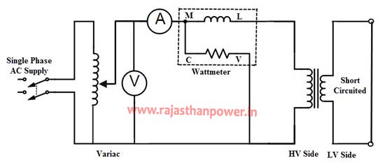
This test is performed to discover series department parameters of an comparable circuit such as identical impedance (Zo1 or Zo2), total winding resistance (Ro1 or Ro2), and total leakage reactance (Xo1 or Xo2). Moreover, it is conceivable to decide copper misfortunes at any wanted load and total voltage drop of the transformer referred to essential or auxiliary. In this test, ordinarily LV winding is shorted by a thick wire. And the other side, i.e. HV side this test is conducted.
distribution transformer vs power transformer
| power transformer | distribution transformer |
| Power transformers are utilized in transmission network of higher voltages for step-up and step down application (200 kV, 400 kV, 66 kV, 110 kV, 33kV) and are generally evaluated over 200MVA. | Distribution transformers are utilized for lower voltage conveyance systems as a implies to conclusion client network. ( 6.6 kV, 11kV, 440V, 3.3 kV, 230V) and are generally appraised less than 200 MVA. |
| Power transformer is utilized for the transmission reason at heavy load, high voltage more prominent than 33 KV & 100% effectiveness. | The distribution transformer is utilized for the conveyance of electrical energy at low voltage as less than 33KV in industrial reason and 440v-220v in domestic reason |
| Power Transformers are utilized in Transmission network so they don’t straightforwardly interface to the customers, so load variances are exceptionally less. | Power Transformers are utilized in Conveyance Network so specifically associated to the consumer so load vacillations are exceptionally high |
| Power transformers are utilized for transmission as a step up gadgets so that the I2r loss can be minimized for a given power flow | Distribution transformers clearly cannot be planned like this. Subsequently the all-day-efficiency comes into picture whereas planning it. |
| The most difference between power and distribution transformer is distribution transformer is outlined for greatest efficiency at 60% to 70% load | Distribution Transformer is utilized at the distribution level where voltages tend to be lower |
Electrical transformers can be classified into different categories depending upon Construction, their end-use, supply and purpose.
On the Basis of Design
- Core Type Transformers
- Shell Type Transformers
On the Basis of Supply
- Single Phase Transformers
- Three Phase Transformers
On the Basis of Purpose
- Step Up Transformers
- Step Down Transformers
On the Basis of Use
- Power transformers
- Distribution transformers
- Instrument transformers
- Current transformers
- Potential transformers
On the Basis of Cooling
- Self-Cooled Oil-Filled Transformers
- Water-Cooled Oil-Filled Transformers
- Air-Cooled (Air Blast) Transformers
Advantages of power transformers:
- High efficiency.(comparison)
- No moving parts
- Less capital cost.(comparison)
- Less maintenance cost.(comparison)
- Easy to move.(comparison)
- Easy to add and remove.]
- Easy to increase or decrease voltage.
- Less monitoring required.
- No starting time.
Disadvantages of power transformer:
- Emits heat and requires a cooling system.
- Works only for ac supply.
| HS Code | Description |
|---|---|
| 85043100 |
Copper Wound Transformer- Ohter Transformers Having A Power Handling Capicity Not Exceeding 1kva- Mpn# E01016 |
| 85043100 |
Copper Wound Transformer- Ohter Transformers Having A Power Handling Capicity Not Exceeding 1kva- Mpn# E00458 |
| 85043100 |
Resin Cast Vt-Model :Ept 11 ( Other Transformer Having A Power Handling Capacitynot Exceeding 1 Kva )We Intend To Cla |
| 85043100 |
Choke/Transformer , Choke , 3-Phase , Item No.: 764030-04h6s F764030-04 , Havinga Power Handling Capacity Not Exceeding |
| 85043100 |
Other Transformers: Having A Power Handlingcapacity Not Exceeding 1kva (P/N:9065713f) (Meis) |
Transformers form the foremost critical connect between supply systems and load. Transformer’s productivity specifically influences its execution and maturing. The transformer’s efficiency, in common, is within the extend of 95 – 99 %. For huge control transformers with exceptionally low misfortunes, the productivity can be as high as 99.7%. So for the reason of effectiveness calculations, OC and SC tests are used to calculate appraised core and winding misfortunes within the transformer.
The efficiency of Power transformers is simply given as:
![]()
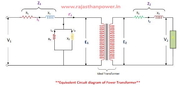
Where,
- R1 = Primary Winding Resistance.
- R2= Secondary winding Resistance.
- I0= No-load current.
- Iµ = Magnetizing Component,
- Iw = Working Component,
The major uses of an electrical transformer/ Power transformers include:
- Isolating two electric circuits.
- Increasing or decreasing the value of an inductor or capacitor in an AC circuit.
- Stepping up the voltage level at the site of power generation before the transmission and distribution can take place.
- Raising or lowering the voltage level in the circuit of an AC.
- Preventing the passage of DC from one circuit to another.
|
|

